CT Floor System


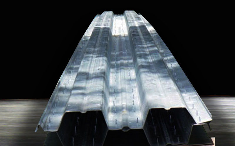
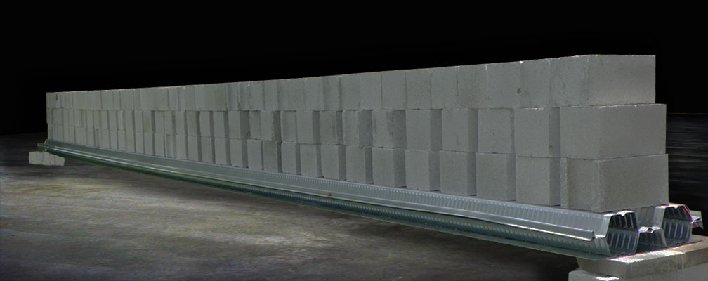
The Classic T system is an ASTM E72 tested   (structural) US Patent #9151048   Prefabricated Floor System engineered to excel at the factors that judge the success of a floor system.


System Properties

  • A ASTM E72 Structural Tested
  • B Self Weight During Crane Lifting:  80 lb for small spans and up to 540 lb for large spans
  • C Final Self Weight:  2" Topping: 50 PSF , 3" Topping: 65 PSF
  • D Up to 29 ft Long Spans with a total true 8" floor thickness.
  • ECore-drilling water readily evacuates cores through pre-drilled holes
  • FEasy to fabricate
  • GFast and Easy Installation
  • HCompatible with usual core-drilling requirements
  • INo Prestressing Tendons
  • JCompetitive pricing
  • KNo joints, it's cast monolithic with beams and exterior balconies.
  • LAbility to control camber, camber fully flat with sole weight of topping.
  • MAfter topping pour, no grouting, welding or leveling agents needed.
  • NFlat, thin body, no dropped elements that can interfere with ducts or lower ceilings.
  • OMinimal shoring  required during construction topping pour
  • PFast to set with a Crane
  • QCompatible With Slab Recesses and Steps
  • R4 Week Lead Time
  • SIn-house Engineering and Drafting
  • SSTC Rating of 65, IIC Rating of 36


We are currently looking to hire a:

-Structural Field Inspector

-Structural Office Engineer/EIT/Designer

-Sales Rep.


Send us a an email: info@ClassicTFloor.com with your CV or contact us via the below contact form.

Contact


STC & IIC Sound Testing

Certified Third Party ASTM Sound Testing Performed by: On-Site Acoustic Testing


Download Sound Test Report: STC & IIC Test Report (PDF)

Information for Contractors
    Crane Installation Video Clip


  • Obtain a Bid From Us:
    • Send us the Structural Framing Plans, from there, we'll calculate the square footage, span length and loading to be applied.
    • Every project has a different cost index based on the steel decking thickness and number of steel deckings required for each span.
    • We send you a bid to fabricate, deliver, erect to final position, shore and certify the installation prior to pour.
    • You place the W1.4 x W1.4 - 6x6 over the system and pour the topping.
  • Shop Drawings:
    • We produce signed and sealed shop drawings and structural calculations showing the floor system layout and section cuts, resembling the layout proposed by the structural framing plans.
    • You get the shop drawings approved by the Architect, Engineer and the G.C.
    • Upon approval we start the fabrication process.
  • Construction:
    • We load the fully assembled modules on a truck and deliver them on site.
    • A crane places the Classic T Modules into final position.
    • The camber is designed to reduce to a flat condition with the weight of the concrete topping, a shoring system would preclude this from happening properly.
    • The system must be shored locally under areas where block pallets are to be temporarily placed.
    • You hook in the rebar over the valleys of the system.
    • You place the WWM over the system and order the topping concrete per the shop drawing compressive strength requirement (varies).
    • The floor is ready.
    • You cure the concrete topping for 7 days
  • Coredrilling:
    • The system is able to handle most coredrilling diameters and layouts, download the following detail for the guidelines to follow.
    • Contact us for layouts and diameters that exceed these parameters.
    • Three pilot holes are pre-drilled into the underside of the hexagon modules to allow the core drilling water to immediately evacuate.
  • Ducts:
    • The system is a thin-type system without any dropped webs or chords.
    • The ducts may freely run underneath the floor.
  • Ceilings:
    • The ceiling framing channels are screwed into the underside of the Classic T light gauge steel, hollow cross section with self drilling screws.
    • When into the composite decking, the framing channels are tapconed into the concrete.
Testing Data

Topping Pour and Construction Live Load

The images below show the steel module bearing the loads of the concrete topping and finishers. Modules were loaded to failure to verify the code required safety factor was obtained.

  • 12 FT - Construction
  • Module: CT222200
  • 15 FT - Construction
  • Module: CT181800
  • 24 FT - Construction
  • Module: CT202000
  • 27 FT - Construction
  • Module: CT181800
  • 30 FT - Construction
  • Module: CT161614
  • Composite (Final) Stage Loading

    The images below show the steel module composite with the hardened concrete after 7 or more days of age bearing the code required superimposed loads. Subsequently, additional load was added to verify the code required safety factors were obtained. The first mode of failure was excessive deflection. This is the preferred mode of failure since it gives a warning to the occupants that the present loads exceed the allowable. The second mode was the sliding of the concrete topping with respect to the screw heads at the ends of the modules. For this reason, more screws are now located at the ends of the modules than at the middle.

  • 15 FT - Construction
  • Module: CT181800
  • 20 FT - Composite
  • Module: CT161600
  • 24 FT - Composite
  • Module: CT202000
  • 27 FT - Composite
  • Module: CT202000
  • 30 FT - Composite
  • Module: CT161614
  • All planks were loaded during their non-composite (construction) stage and composite stage (final). Deflections are given at every interval.

    The following section shows images from the gravity, deflection and vibration testing for the Classic T system during the construction stage and final stage.

    Since the system is self supporting during the topping concreting operation, we tested the planks by loading it with 8x8x16 hollow CMU block. Block was placed at spacings and in quantities to represent the weight of the concrete topping alone, in which casee we verified that the camber always reduced to zero.


    This is the load that will stay while the concrete hardens and how the composite section will start. During the concreting operation, we considered the weight of the workers as well, 20 psf is specified by SDI. In all cases the system remained strong and showed little deflection at this loading level. The SDI requires us to assume the scenario where an uncontrolled concreting operation will cause concrete to build up, and apply a heavier load than the 2" topping considered. For this case and to obtain the general factor of safety for each design, we loaded the plank to failure.

    The procedure for testing of the final composite stage was also tested for increasing levels of loadings, as the images shown. In all cases, the deflection stayed within the limits when applying a superimposed load of 80 PSF which was selected because it considers the heaviest loading with which custom homes are designed when thick marble panels are set on a thick mortar bed. The system was then loaded to failure in all cases to successfully verify that the mode of failure was ductile and with excessive deflections as is desired. No brittle or sudden failures were observed.

    The titles of the images indicate the factor of safety achieved or the level of overloading that was being tested above the code required loading. For the construction stage, the basis is the 20 PSF live load. For the Final stage, the basis is the 80 PSF superimposed load.

    Information for Architects

    The Classic T is a Flat Floor of 8" of Total Thickness:

    • This allows for high ceilings and coffered ceilings.
    • This allows for a cumulative story height reduction (more stories in the building for a given zoning height restriction).
    • The steel decking at the bottom (corrugated or flat sheet, as required by design) is in tension.
    • True actual 8" net thickness. Other prefabricated systems do not become flat after the topping pour, and since the contractor is instructed to provide a minimum topping thickness (to prevent cracking) he measures the 2" from the HIGHEST point of the camber. Resulting in slab thicknesses of up to 4" at the ends. This means inevitably 2" of lost ceiling height. This does NOT happen with the Classic T Floor system.

    The Classic T is Long Spanning - Up to 30ft - for a total thickness of 8".:

    • This allows for more open, free of intermediate supports areas in your project.

    The Classic T is STC and IIC Tested:

    • Equivalent STC Rating of 65
    • Equivalent IIC Rating of 36

    Information For Structural Engineers

    The Classic T is a Composite Floor System

    • The concrete topping acts in compression.
    • The self drilling screws and composite decking corrugations, along the module's length transfer the longitudinal shear from the concrete to the steel decking at the bottom.
    • The steel decking at the bottom (corrugated or flat sheet, as required by design) is in tension.

    The Classic T is Cambered and Pre-stressed:

    • To build the Classic T Module, we jack upward both corrugated steel deckings from the mid point to give it a desired camber. The upper decking enters in tension and the bottom decking in compression, which grants pre-stresses that are inverse of the service load stresses. The self drilling screws then connect both deckings together at very frequent spacings along the length of the module. There are more screws at the ends than at the middle, following the shear diagram. The screws have locked in the camber and prestress and the system is now ahead of the game in it's deflection and stress journey.

    The Classic T is Light:

    • The large hexagonal voids formed by the corrugated steel decking arrangement are excellent at reducing the amount of concrete to the bare minimum required for compressive resistance and longitudinal shear transfer.
    • Any intermediate steel or concrete beams bearing the system are able to be reduced in linear weight.
    • The system can have a 2" or 3" topping depending on the "cost vs. feel-solid performance" required for each project
    • The cumulative effect of weight reduction, over multiple stories will help reduce sectional area and reinforcing in columns and foundations.

    The Classic T achieves longer Spans for the Same Thickness:

    • There will be less girder beams, columns and pad footings in general.
    • The load path is more uniform (less concentrated) and therefore more distributed and reliable.
    • There are less connections
    • There are less elements to structurally design and detail

    The Classic T has Excellent Long Term Deflection Performance:

    • Due to the steel module cambering and load carrying capacity, the topping concrete begins it's composite life at  zero stress. Under the full system self weight, there is no concrete in compression.
    • The composite topping becomes stressed in compression only as the superimposed dead loads are applied after curing. The majority of the permanent dead weight is, fortunately the weight of the module and concrete topping themselves, which don't contribute to long term deflection, since they are entirely carried by the steel module.
    • The topping concrete strength is critical to reduce it's compressive creep and therefore long term bending deflections. We proportion  it up to a strength of 5000 psi for the longer spans.
    • The cambering allows the composite plank to begin its life at zero deflection.

    The Classic T Has Been Tested:

    • Non - Composite (During Topping Pour) Gravity Load and Release Cycles to Failure
    • Composite 20FT - (Final Stage) Gravity Load and Release Cycles to Failure
    • Composite 23FT and 30FT - (Final Stage) Gravity Load and Release Cycles to Failure
    • Foot Traffic - 500lb force - 1000 cycles
    • Shear Capacity - Incremental Load to Failure
    • Cyclic Gravity to Full Service Load / Cyclic Uplift - Wind Gusts
    • Uplift Pressure - Incremental Loads to Failure
    • Shear Non Composite - Incremental Load To Failure
    • 24 Hour Sustained Gravity Full Service Load
    • Decking Tensile 16 Gauge
    • Decking Tensile 18 Gauge
    • Decking Tensile 18 Gauge-2
    • Concrete Compressive Test

    Architectural Features:

    • The system can be used to develop top rebars that reinforce cantilevered concrete slabs.
    • The system can accomodate up to 4" shower recesses and overpoured platforms up to 4" tall.

    Limitations:

    • Due to the underside of the decking being exposed galvanized steel, the system may not be specified where the underside of the steel decking will be exposed to the exterior weather.
    • Larger than 8" wide (measured across the main system structural direction) must be provided with a slab beam to either side of the opening.
    • The system cannot be used to support large concentrated loads such as load bearing masonry walls.
    ASTM E72 Structural Testing

    Certified Third Party ASTM E72 Testing Performed by: Hurricane Engineering & Testing Inc.


    Full list of Reports for the Testing Performed:


    Download All Reports and Drawings as a Single PDF File


    Videos of some of our modules being tested

    Non Composite 23ft Clear Span Gravity Load Test, 100 psf

    Composite 20ft clear Span Uplift Load Test, 240 psf

    Composite 23ft Clear Span Gravity Load Test, 220 psf

    Composite Shear, (1) 4" diameter perforation

    Composite 23ft Clear Span Cyclic Gravity Testing

    Finalized Projects: Click on the Image Icons to see detail pictures
  • Prefabricated Floor Area: 3 600 sqft
  • Maximum Span: 23.5 ft
  • Fabrication Time: 5 days
  • Installation: 1 day by Crane
  • Prefabricated Floor Levels 1
  • Prefabricated Floor Area: 4 300 sqft
  • Maximum Span: 26 ft
  • Fabrication Time: 5 days
  • Installation: 3 days by Crane
  • Prefabricated Floor Levels 1
  • Prefabricated Floor Area: 11 000 sqft
  • Maximum Span: 25.5 ft
  • Fabrication Time: 10 days
  • Installation: 2 days by Crane
  • Prefabricated Floor Levels 2
  • Prefabricated Floor Area: 3200 sqft
  • Maximum Span: 23 ft
  • Fabrication Time: 5 days
  • Installation: 1 day by Crane
  • Prefabricated Floor Area: 3000 sqft
  • Maximum Span: 19 ft
  • Fabrication Time: 5 days
  • Installation: 1 day by Crane
  • Prefabricated Floor Area: 280 sqft
  • Maximum Span: 19 ft
  • Fabrication Time: 1/2 day
  • Installation: 1/2 day by Hand
  • Prefabricated Floor Area: 4700 sqft
  • Maximum Span: 22 ft
  • Fabrication Time: 6 days
  • Installation: 1 day by Crane
  • Prefabricated Floor Area: 1700 sqft
  • Maximum Span: 22 ft
  • Fabrication Time: 3 days
  • Installation: 2 days by Front Loader
  • Prefabricated Floor Area: 378 sqft
  • Maximum Span: 27 ft
  • Fabrication Time: 3 days
  • Installation: 1 day by hand
  • Contact


    Interested in fabricating and installing the system?

    Are you a builder, a steel decking manufacturer, a structural steel fabricator or a floor system fabricator seeking to expand on your product line? One of the most important features of the Classic T Floor System is its extreme ease of fabrication and low investment cost (less than $800) to start fabricating. In general, what one would need is:

    • A Warehouse Space or a Yard with a relatively flat concrete slab as the assembly floor.
    • 2x4 nailed to a CMU wall
    • A 2000 lb red jack
    • A truck to deliver the modules to the site
    • A crane to set the modules in their final position

    As you can see, there are is no large, heavy and anchored prestressing equipment, strands, welding, bridge cranes, long casting beds or waiting for precast concrete to cure! We encourage you to become a fabricator of our system, start by giving us a call or writing us an email.


    Downloads Page Reference Structural Plans Showing the Use of the CT Details and Plan Layouts

    12000 sqft home
    4700 sqft home


    CAD Details

    CAD Details
    Frequently Asked Questions

    How is the ceiling attached to the Classic T?

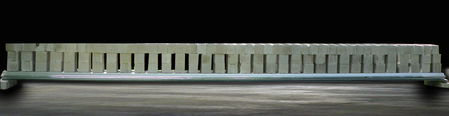
    1 - When attaching to the void light gauge hexagons, usually #10 tek screws fasten 20 gauge C-channels

    2 - When attaching to the single steel decking that is in contact with concrete, use 1/4" tapcons, there is no risk in drilling for tapcons to the underside of the module since the floor does not have any type of prestressing steel.


    Can the Classic T be core drilled for plumbing and Air Conditioning ducts?

    1 - Up to 4" cores for plumbing are usual and acceptable, we include a typical detail showing the acceptable hole diameters, arrangements and required clear spacing between them. The floor has been specifically tested for shear resistance under this scenario.

    2 - A/C openings usually exceed the capability of the module and must be identified ahead of time in order to prepare the edges of the system for the opening. Some exception cases such as when the opening is directly adjacent to a supporting wall or beam may not require special treatment.


    Will the core-drilling cooling water accumulate inside the hexagons?

    Each hexagon is pre-drilled during fabrication with 3 drainage holes with the sole purpose of fully evacuating all rain and core drilling water.


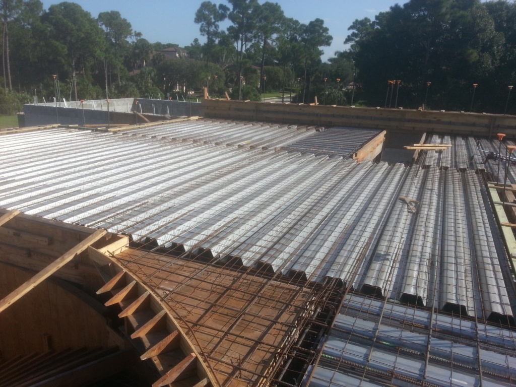
    How can I be certain that the 16" length at the ends of the modules will be filled with concrcete as the details show?

    We have observed how different slumps of pea-rock concrete shape and fill the end portions of the hexagon and we have concluded that a 7" slump pea-rock (3/8" max aggregate size) will nicely flow into the hexagon and readily taper down in the required shape. This way there is no need for the worker finishing the concrete to be aware of the need to fill the end of the hexagon, it happens automatically.


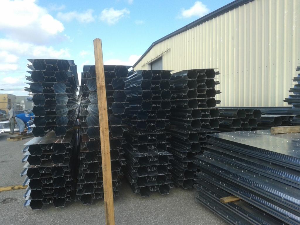
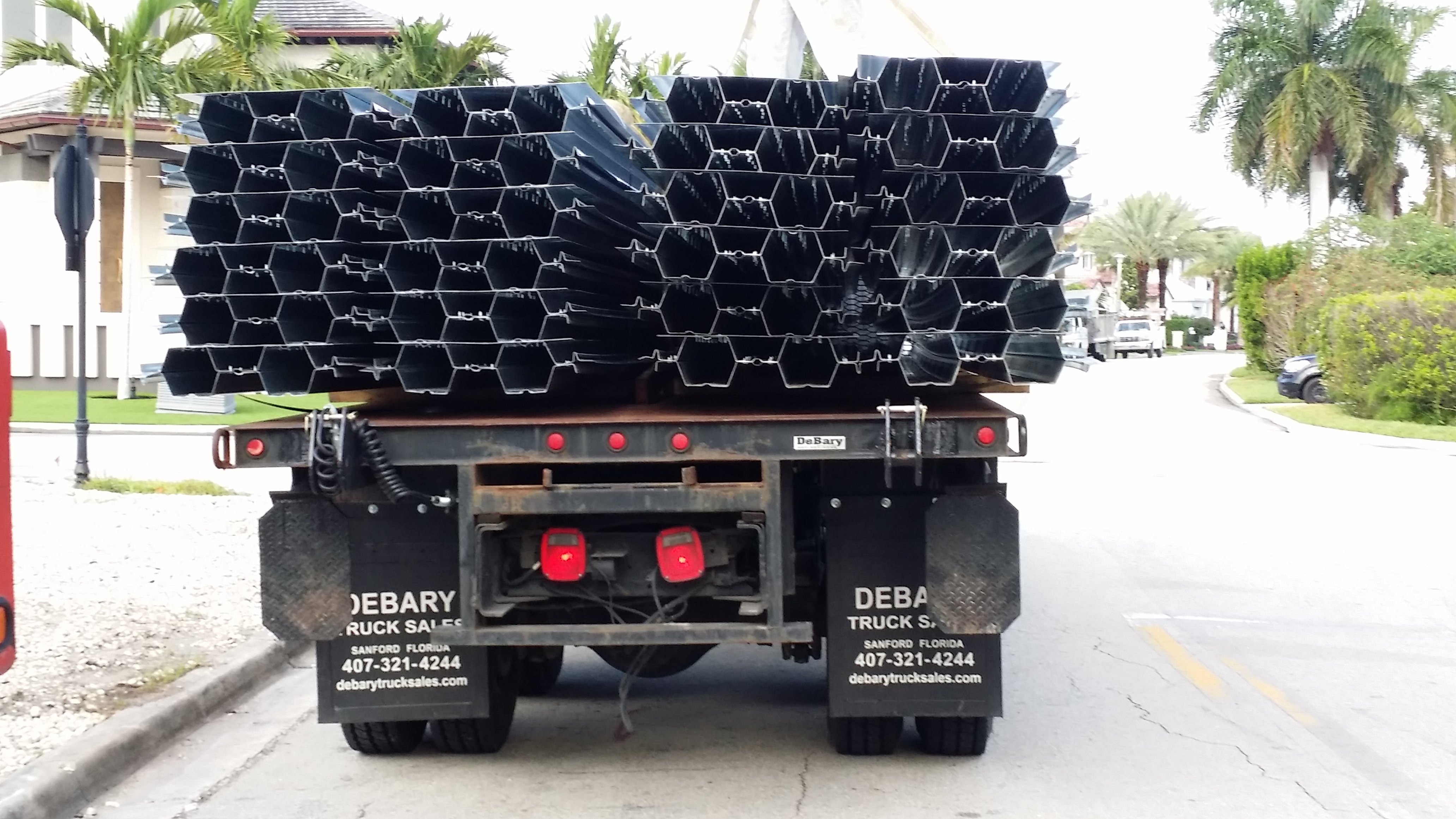
    From the day I place the order for the material, how long will it take until the material is on site?

    1 - If we are shipping only the steel decks for site fabrication, usually no more than 2.5 weeks.

    2 - If we are shipping the assembled modules, it is usually no more than 4 weeks.


    In a two story structure, where the CT is the second floor, when can I remove the post shores?

    We suggest to leave the shoring until all CMU blocks have been used on the 2nd floor walls and they are no longer weighing on the CT floor. At that point, as long as the concrete is a minimum of 7 days old and has reached a concrete strength of 3000 psi.


    How do I shore the modules before the pour and how do I shore in the middle of the span where the module is cambered?

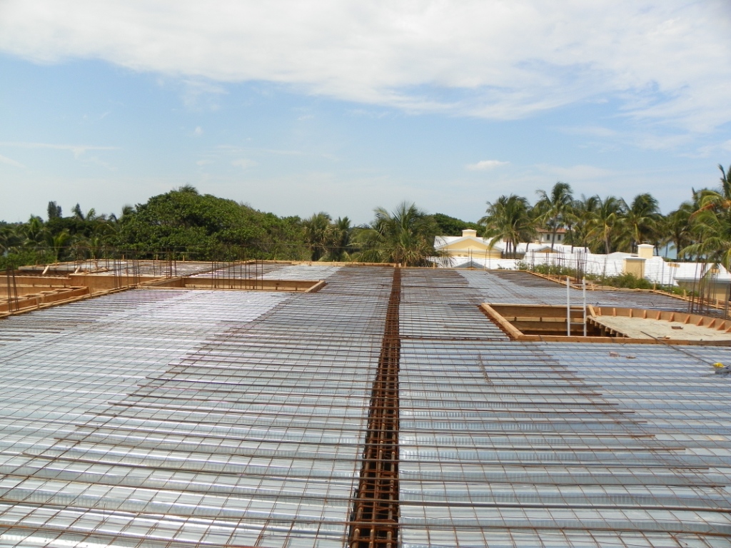
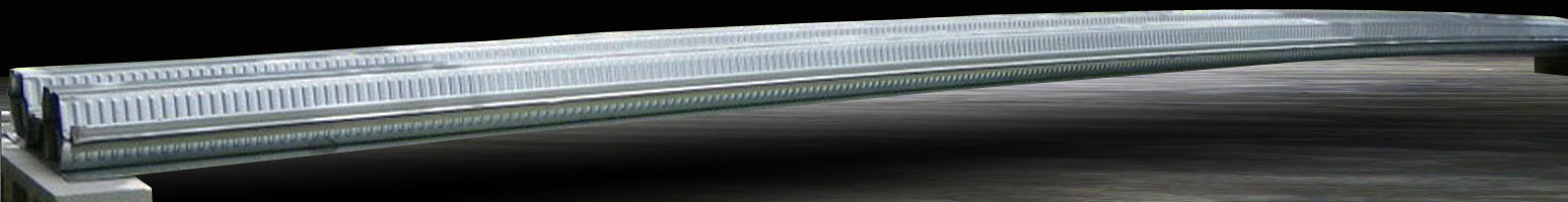
    We show the shoring in the shop drawings. This usually consists on 3 lines of shoring running perpendicular to each span. The lines closest to the ends are in direct contact with the underside of the steel decking. The mid span shoring line is not in contact with the underside of the module before the pour, but will be as the fresh concrete topping weight flattens the camber.

    So initially all tops of shoring beams must be at the same level and it equals the top of the waler member near the tie beams. For example, if the floor consists of a 2" topping and a 6" deep hexagon, the top of the waler and shoring beams will be 8" below finished slab elevation.

    Look out for changes in the layout that require a different waler elevation, such as when we have short spans and use a composite steel deck by itself


    Do I pour the topping after or together with the walls, columns and tie beams?

    The walls and columns are optionally poured first, up to "beam bearing height". Shell contractors elect this when they need to strengthen high walls or when they think the slab finishers will be non productive while waiting for the walls to be poured. We always prefer the topping be poured together with the tie beams and slabs in order to have a "single mat of concrete" with "no construction joints" that are exposed to the exterior and could become a passage for the rain water to get inside the house.


    The steel decking doesn't perfectly fit around the returs and jogs of my tie beam

    The Classic T is made of light gauge steel and can be easily field trimmed back and around the supports to fit.


    Can the Classic T be used exposed to the weather?

    Not When within the reach of the ocean breeze. The modules are made of steel, and although they are galvanized, the steel will corrode under the salt spray of the ocean breeze. For projects near the ocean, the Classic T is only specified to be within enclosed spaces. The top surface can be exposed to the weather since it has a minimum of 2" concrete coverage, but the bottom surface of the floor cannot.


    Can I incorporate recesses into the Classic T, if so how deep can they be?

    Yes, and up to 4". We smoothly "bridge under" the recesses to build up an additional concrete thickness so after recessing, we will have a 2" topping over the module. Please see our details in the shop drawings.


    Enter Your Address or Zip Code: